
This is a guest post written by Roy Green of The Sensor Shack , a free online resource for engineers to learn about different types of industrial sensors for measuring temperature, pressure, flow rate, displacement and more.
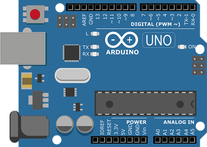
Arduino boards are a range of low cost open source microcontrollers ideal for DIY projects including robotics, drones and environmental monitoring. Although their processing power and RAM are limited, Arduinos have the advantage of being easy to program (there are many free resources and extensive libraries) and include a large number of I/O pins (input/output pins). The I/O pins enable the Arduino to control actuators, receive sensor inputs and communicate with external devices. The types of Arduino pins include:
Arduino Pins for I/O sensors
- Analog output pins: Output analog voltages between 0-5 V (0-3.3 V on 3.3 V boards). The output is not truly analog but rather 1 of 256 discrete voltages levels (for an 8 bit digital to analog converter ). Analog outputs are useful for controlling actuators, many of which require an analog control signal.
- Analog input pins: Accept analog input voltage signals between 0-5 V (0-3.3 V on 3.3 V boards). The voltage is converted into one of 1024 discrete voltages by the Arduino’s 10 bit analog to digital convert (ADC). Analog inputs are useful for reading sensors (e.g. thermocouples and pressure sensors ). Furthermore, an analog input pin can be used to connect a potentiometer (e.g. as a DC motor speed controller).
- Digital output pins: Output either 0 V or 5V. They are useful for providing commands and, with the aid of relay switches, can be used to power DC motors and other actuators:
- Digital input pins: Accept either a logic 0 (input < 2.5 V) or logic 1 (input >2.5 V) input signal. They are useful for connecting buttons and switches to the Arduino.
- PWM pins: PWM is an abbreviation for pulse width modulation. It describes a technique where a digital output pin is pulsed on and off at high frequency. The PWM can be used to switch a power supply on and off (via solid state relay) to regulate the time averaged voltage received by an actuator. They are often used as a simple and low cost method for controlling DC motor speed.
- Serial communication: Serial communication by protocols such as I2C can be used to communicate with external devices. It enables large quantities of data to be sent and received.
Basic Arduino programming commands
There are many different Arduino boards to choose from, descriptions of which can be found on the official Arduino website https://www.arduino.cc/en/main/products . Differences between them include their physical size, the number and type of ports, processor speed, memory, and operating voltage (either 3.3 V or 5 V). There is a wealth of information on the internet to aid in selecting a board, though the Arduino Uno is generally considered a good entry level board. We will now look a few of the basic commands for programming Arduinos. More information about each command can be found on the Arduino website https://www.arduino.cc/reference/en/#functions .
- Int: Int is short for integer and is one of the many available data types. To read the output from a sensor, we must first define a variable to store the data. This requires us to also choose a datatype for the variable. For example, int X =0 defines variable X as an integer with an initial value of 0. If we want X to be able to take on non-integer values, we can choose to define X as a floating point number using , float X =0.
- PinMode(pin,value): Configures a digital pin as either an input or output pin. This is required because each digital pin can serve as an input or an output. For example, PinMode(1, INPUT) and PinMode(2, OUTPUT) set pin 1 to input and pin 2 to output. Note that the default value for all digital pins is input.
- digitalRead(pin): The command is used to sample the level of a digital input pin and return either logic 0 or 1. For example, X=digitalRead(1) will sample digital pin 1 and assign either a logic 0 or logic 1 to variable X.
- digitalWrite(pin, value): The command is used to switch an output pin to either 0 V or 5 V. For example, digitalWrite(2, HIGH) will switch pin2 to 5 V.
- analogRead(pin): The command is used to sample an analog input pin and return a discrete value. Assuming a 10 bit ADC, a value between 0 and 1,023 will be returned, where 0 is 0 V and 1,023 is 5 V.
- analogWrite(pin, value): The command is used to output a voltage between 0 and 5 V. Assuming an 8 bit DAC, there are 256 discrete voltages that can be outputted (represented by the integers 0 to 255). For example, the command analogWrite(2, 127) will output 2.5 V on pin 2.
- max(): Returns the larger value of two variables. For example, if A=10 and B=20, the function C=max(A,B) will return C=20. Similar functions include min and abs which return the minimum and absolute values respectively.
- sq(): Returns the square of a number. Related functions include sqrt and power which return the square root of a number and the number raised to a specified power respectively.
- delay(): Causes the controller to pause for a specified amount of time e.g. delay(500) causes a 500 millisecond delay.
- micros(): A timer which counts the number of microseconds elapsed since the command was called. A related function, millis, returns the number of milli seconds elapsed.
- if(): The if function is a logic function which returns one value IF a certain condition is true and a different value if it is false. For example, if we are measuring temperature with a thermocouple and want to know when the temperature is over 20 °C, we could use an if function to return a value of 0 if temperature is under 20 °C and a value of 1 if temperature is over 20 °C.
- for(): The for function is used to repeat a block of code multiple times. An example is for measuring temperature using 10 RTD sensors on different pins. Imagine that the program uses an equation to calculate temperature from the input voltage. Instead of typing out the equation 10 times (which uses lots of memory) the for function can be used to apply the equation 10 times.
- while() Whilst a condition is true, the code within the while loop runs continuously.
- Serial.print: The command sends text or numbers to the serial monitor of the Arduino IDE. This provides a simple method of receiving information from the Arduino microcontroller. Serial.print(X) sends the value stored in variable X. Serial.print(“X”) sends the letter X. A related command, Serial.println, jumps to new line after sending the data.
Arduino program for sampling a thermocouple temperature sensor
We will now look at a simple code using several of the above functions. The example code reads the analog voltage from 2 temperature sensor breakout boards, calculates temperature and prints the data to the serial monitor. Every Arduino code has two sections: void setup() and void loop(). Code entered into void setup() runs once as soon as the Arduino is switched on. Code entered in void loop() runs in a continuous loop.
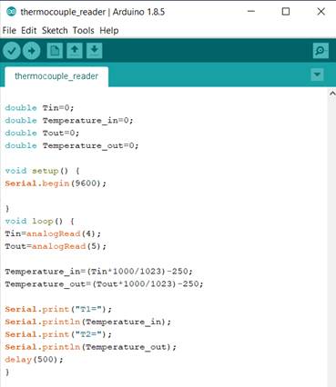
- We define our 4 variables, Tin, Tout, Temperature_in and Temperature_out as data type double, with initial values of 0.
- We add the code Serial.begin(9600) to our void setup(). This sets the Baude rate for serial communication to 9600 and is necessary in order for the serial.print command to work.
- We DO NOT need to use the function pinMode() because we are only using analog pins.
- We use analogRead() to sample the temperature sensor voltages on pins 4 and 5.
- We calculate the temperature from the voltages using a simple equation. We then store the temperatures inside variables Temperature_in and Temperature_out.
- We use Serial.print to send the temperature data to the serial monitor in the Arduino IDE.
- We use the delay() function to force the controller to wait for 0.5 seconds before returning to the start of the program and resampling pins 4 and 5.
More Resources